BS 6883&BS7917 Offshore & Marine cables
3.8/6.6kV, 6.35/11kV, 8.7/15kV HF-EPR Insulated, SW2/SW4 Sheathed Unarmoured Flame Retardant Power & Control Cables (Radial Field)
Application
These medium voltage elastomeric insulated cables are designed for fixed wiring in ships and on mobile offshore units, suitable for use in power and control applications.
Standards
- BS 6883
- IEC 60332-3A Flame retardant
- IEC 60754-1; IEC 60754-2 Corrosivity
- IEC 61034-2 Smoke density
- Cold bend and impact (-40°C) (on request)
- CSA C22.2 No. 38-95 (on request)
Construction
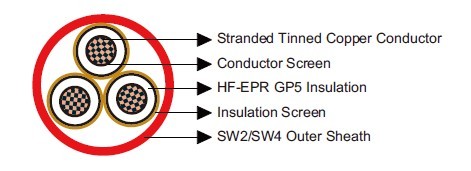
- Conductor: Tinned copper wire stranded circular cl. 2 BS 6360/IEC 60228.
- Conductor Screen: Semiconducting layer or tape.
- Insulation: HF-EPR GP5 according to BS 7655 1.2.
- Insulation Screen: Semiconducting layer or tape +Tinned copper tape.
- Outer Sheath: Halogen free thermosetting compound SW4 according to BS 7655 2.6 or reduced halogen thermosetting compound SW2 according to BS 7655 2.6.
Mechanical and Thermal Properties
- Minimum Internal Bending Radius: 15×OD (single core); 20×OD (three core)
- Temperature Range: -40℃ ~ +90℃
Dimensions and Weight
3.8/6.6kV
| Construction No. of cores×Cross section(mm²) |
Nominal Insulation Thickness mm |
Nominal Outer Sheath Thickness mm |
Minimum Overall Diameter mm |
Maximum Overall Diameter mm |
Approx. Weight kg/km |
| 1×16 | 3.0 | 1.3 | 16.0 | 18.0 | 492 |
| 1×25 | 3.0 | 1.3 | 17.6 | 19.7 | 658 |
| 1×35 | 3.0 | 1.4 | 18.7 | 20.8 | 776 |
| 1×50 | 3.0 | 1.4 | 19.9 | 22.3 | 942 |
| 1×70 | 3.0 | 1.5 | 21.8 | 24.3 | 1229 |
| 1×95 | 3.0 | 1.6 | 23.7 | 26.3 | 1546 |
| 1×120 | 3.0 | 1.6 | 25.4 | 28.0 | 1890 |
| 1×150 | 3.0 | 1.7 | 27.0 | 29.8 | 2242 |
| 1×185 | 3.0 | 1.8 | 29.0 | 32.1 | 2713 |
| 1×240 | 3.0 | 1.9 | 31.7 | 35.0 | 3427 |
| 1×300 | 3.0 | 2.0 | 34.3 | 37.6 | 4177 |
| 1×400 | 3.0 | 2.1 | 37.6 | 41.1 | 5145 |
| 1×500 | 3.2 | 2.3 | 41.4 | 45.5 | 6408 |
| 1×630 | 3.2 | 2.4 | 45.1 | 49.2 | 8134 |
| 3×16 | 3.0 | 1.8 | 32.7 | 36.0 | 1482 |
| 3×25 | 3.0 | 2.0 | 36.5 | 39.9 | 2031 |
| 3×35 | 3.0 | 2.0 | 38.4 | 41.9 | 2359 |
| 3×50 | 3.0 | 2.2 | 41.3 | 45.3 | 2918 |
| 3×70 | 3.0 | 2.3 | 45.3 | 49.4 | 3788 |
| 3×95 | 3.0 | 2.5 | 49.3 | 53.9 | 4776 |
| 3×120 | 3.0 | 2.6 | 53.1 | 57.8 | 5868 |
| 3×150 | 3.0 | 2.7 | 56.5 | 61.4 | 6933 |
| 3×185 | 3.0 | 2.9 | 60.8 | 66.1 | 8401 |
| 3×240 | 3.0 | 3.1 | 66.6 | 72.2 | 10616 |
6.35/11kV
| Construction No. of cores×Cross section(mm²) |
Nominal Insulation Thickness mm |
Nominal Outer Sheath Thickness mm |
Minimum Overall Diameter mm | Maximum Overall Diameter mm |
Approx. Weight kg/km |
| 1×16 | 3.4 | 1.3 | 16.8 | 18.8 | 524 |
| 1×25 | 3.4 | 1.4 | 18.6 | 20.7 | 704 |
| 1×35 | 3.4 | 1.4 | 19.4 | 21.9 | 813 |
| 1×50 | 3.4 | 1.5 | 20.8 | 23.3 | 994 |
| 1×70 | 3.4 | 1.5 | 22.6 | 25.1 | 1272 |
| 1×95 | 3.4 | 1.6 | 24.4 | 27.1 | 1592 |
| 1×120 | 3.4 | 1.7 | 26.3 | 29.0 | 1956 |
| 1×150 | 3.4 | 1.7 | 27.8 | 30.6 | 2294 |
| 1×185 | 3.4 | 1.8 | 29.8 | 32.9 | 2769 |
| 1×240 | 3.4 | 1.9 | 32.5 | 35.8 | 3487 |
| 1×300 | 3.4 | 2.0 | 35.0 | 38.4 | 4242 |
| 1×400 | 3.4 | 2.1 | 38.4 | 41.9 | 5208 |
| 1×500 | 3.4 | 2.3 | 41.8 | 45.8 | 6442 |
| 1×630 | 3.4 | 2.4 | 45.5 | 49.6 | 8176 |
| 3×16 | 3.4 | 1.9 | 34.5 | 37.9 | 1601 |
| 3×25 | 3.4 | 2.0 | 38.2 | 41.6 | 2139 |
| 3×35 | 3.4 | 2.1 | 40.2 | 44.1 | 2497 |
| 3×50 | 3.4 | 2.2 | 43.0 | 47.0 | 3040 |
| 3×70 | 3.4 | 2.4 | 47.1 | 51.3 | 3949 |
| 3×95 | 3.4 | 2.5 | 51.0 | 55.6 | 4919 |
| 3×120 | 3.4 | 2.7 | 55.0 | 59.8 | 6055 |
| 3×150 | 3.4 | 2.8 | 58.4 | 63.3 | 7132 |
| 3×185 | 3.4 | 3.0 | 62.7 | 68.1 | 8613 |
| 3×240 | 3.4 | 3.2 | 68.5 | 74.1 | 10848 |
8.7/15kV
| Construction No. of cores×Cross section(mm²) |
Nominal Insulation Thickness mm |
Nominal Outer Sheath Thickness mm |
Minimum Overall Diameter mm |
Maximum Overall Diameter Mm |
Approx. Weight kg/km |
| 1×25 | 4.5 | 1.5 | 20.9 | 23.4 | 808 |
| 1×35 | 4.5 | 1.5 | 21.7 | 24.3 | 921 |
| 1×50 | 4.5 | 1.5 | 22.9 | 25.5 | 1110 |
| 1×70 | 4.5 | 1.6 | 24.9 | 27.5 | 1396 |
| 1×95 | 4.5 | 1.7 | 26.7 | 29.5 | 1726 |
| 1×120 | 4.5 | 1.8 | 28.6 | 31.4 | 2099 |
| 1×150 | 4.5 | 1.8 | 30.1 | 33.3 | 2445 |
| 1×185 | 4.5 | 1.9 | 32.1 | 35.3 | 2929 |
| 1×240 | 4.5 | 2.0 | 34.8 | 38.2 | 3661 |
| 1×300 | 4.5 | 2.1 | 37.3 | 40.8 | 4429 |
| 1×400 | 4.5 | 2.2 | 40.7 | 44.6 | 5390 |
| 1×500 | 4.5 | 2.4 | 44.1 | 48.2 | 6638 |
| 1×630 | 4.5 | 2.5 | 47.8 | 52.0 | 8415 |
| 3×25 | 4.5 | 2.2 | 43.1 | 47.1 | 2458 |
| 3×35 | 4.5 | 2.3 | 45.2 | 49.2 | 2832 |
| 3×50 | 4.5 | 2.4 | 47.9 | 52.1 | 3395 |
| 3×70 | 4.5 | 2.6 | 52.1 | 56.7 | 4336 |
| 3×95 | 4.5 | 2.7 | 55.9 | 60.7 | 5334 |
| 3×120 | 4.5 | 2.9 | 59.9 | 64.9 | 6500 |
| 3×150 | 4.5 | 3.0 | 63.3 | 68.7 | 7602 |
| 3×185 | 4.5 | 3.2 | 67.6 | 73.2 | 9116 |
